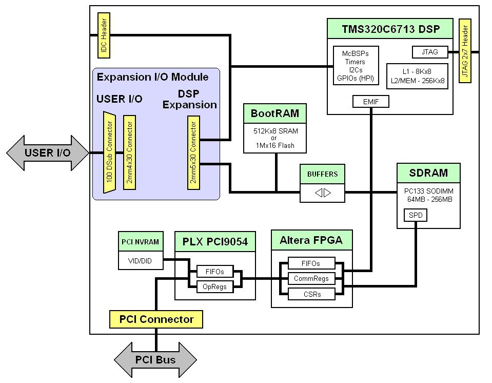
Processor for SI-C6713DSP
[table class=”siTB”]
TI 300MHz TMS320C6713[attr colspan=”2″]
MIPS/MFLOPS, 2400/1800
DMA Channels, 16 (2 dedicated for PCI bus)
L1 Program Cache/SRAM, 4KB
L1 Data Cache/SRAM, 4KB
L2 Cache/SRAM, 256KB
[/table]
External Memory
[table class=”siTB”]
SDRAM Memory[attr colspan=”2″]
Type/Speed, Standard 3.3V; non-buffered PC133 SO-DIMM module clocked from DSP’s E Clock running at 75Mhz
Sizes[attr rowspan=”2″], 64MByte (16Mx32)
256MByte (64Mx32)
Mapping[attr rowspan=”2″], CE2: DSP memory region starting at 0xA0000000
CE3: DSP memory region starting at 0xB0000000
[/table]
[table class=”siTB”]
Boot Memory[attr colspan=”2″]
Type/Size, 512kx8 SRAM or 2Mx8 NOR Flash memory
Configuration, Dual Access memory: Accessible by host (only while DSP is inactive/reset) for downloading COFF files. Accessed by DSP during its boot loading process
Mapping, CE1: DSP memory region starting at 0x90000000
[/table]
Interfaces
[table class=”siTB”]
PCI Interface between Host PC and DSP[attr colspan=”2″]
Active Communication Modes[attr rowspan=”2″], Data Transfers: Bus master DMA and target mode
Messaging with user defined mailboxes
Transfer Rates[attr rowspan=”2″], Burst Transfers: Up to 132Mbyte/sec with block sizes of eight (8) 32 bit words
Sustained Transfers: Up to 12Mbyte/sec with any block size using DMA
[/table]
Connectors
[table class=”siTB”]
Port Connectors[attr colspan=”2″]
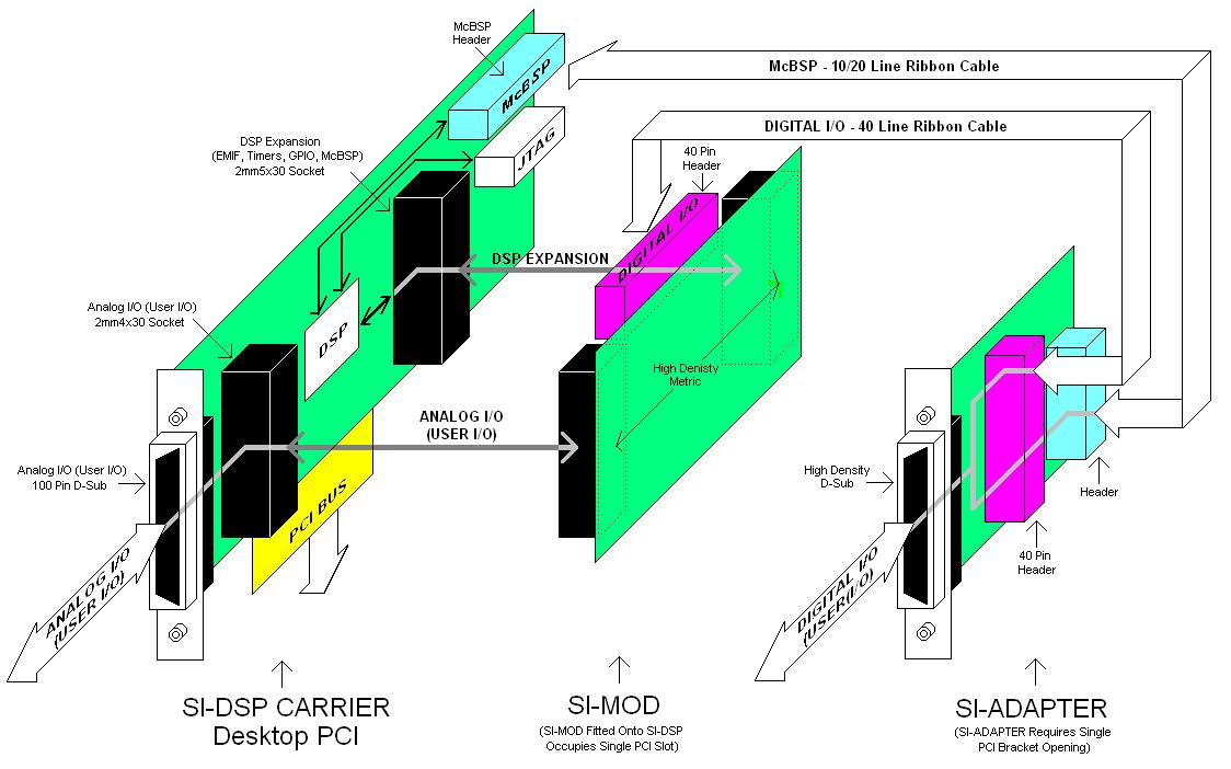
PCI[attr rowspan=”4″], Desktop PCI: One Edge connector
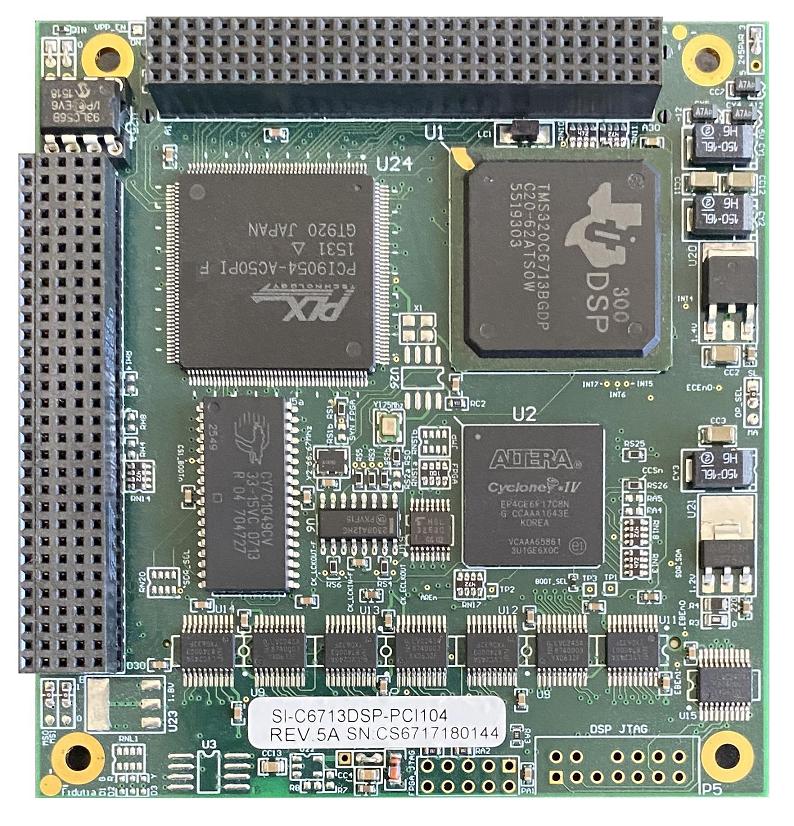
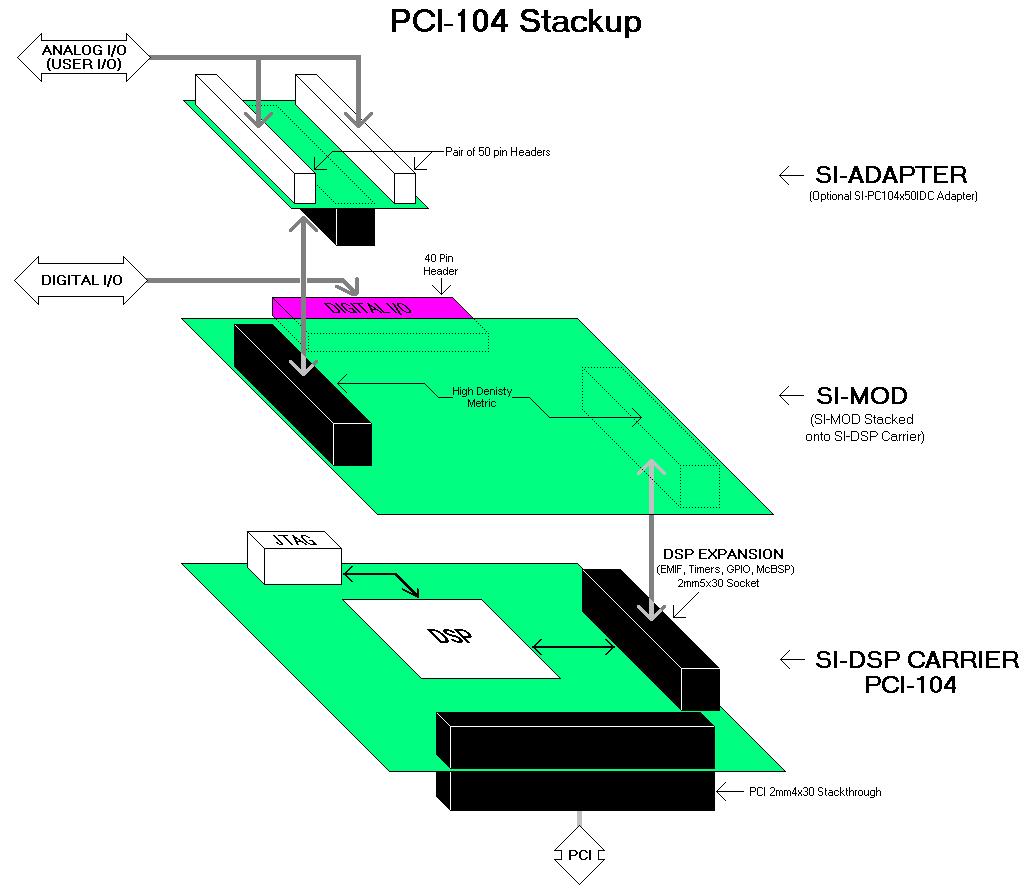
PCI-104: One 120 pin (2mm 4×30) stacking connector
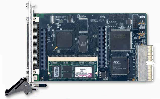
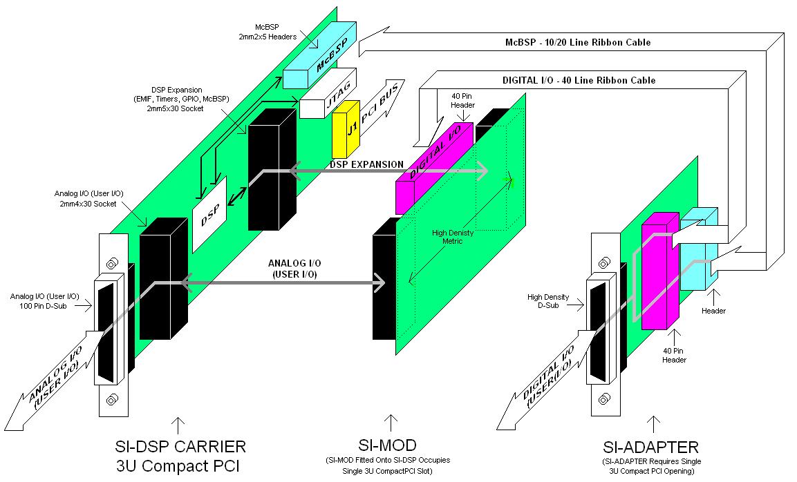
3U CompactPCI: One 110 pin (2mm 5×22) Type A Backplane connector
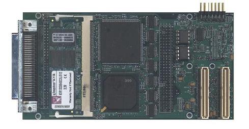
PMC: Two 64 position Mezzanine connector
JTAG, One 14 pin (2×7) header
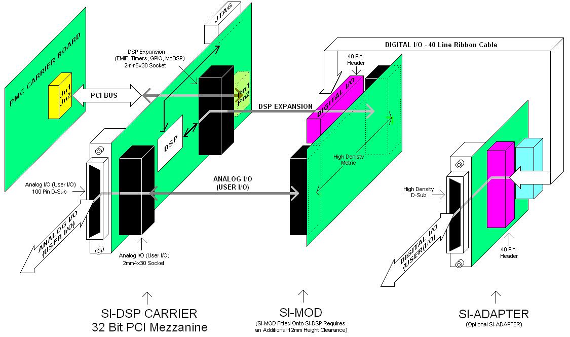
EMIF (DSP Expansion), One 150 pin (2mm 5×30) Peripheral Expansion connector
GPIOs & Timers (Desktop PCI only)[attr rowspan=”2″], One 50 pin (2×25) header: McBSP1 – TINP[1:0] – TOUT[1:0]
One 10 pin (2×5) header: McBSP0
[/table]
[table class=”siTB”]
Peripheral Expansion[attr colspan=”2″]
DSP Expansion[attr rowspan=”2″], First external 2mm pitch: 150 pin (5×30) socket connector for interfacing the expansion module to all of the DSP’s peripheral ports (EMIF – McBSP – McASP – HPI/GPIO – Timers)
DSP EMIF bus: Isolated using LVC2245 buffers. Decodes 64kx32 words mapped on CE1 with Address (A[15:0]); Data (D[31:0]); Control (X_R/Wn – X_CSn – X_INT[1:0] – X_RDY – X_CLK[1:0]); and Power (3.3V; +/-12V; 5V; 1.8V)
User I/O[attr rowspan=”2″], Externally accessible user I/O 100 pin connector: half pitch (0.050″); Series III DSUB for interfacing external user defined signals to the 2mm User I/O connector. AMP part 787169-9; 787170-9; or 787362-9
Second external 2mm pitch: 120 pin (4×30) socket connector for interfacing external user defined signals to custom daughter module. Linked only to externally accessible 100 pin half pitch DSUB connector
[/table]
Mechanical Properties
[table class=”siTB”]
Physical Dimensions/Electrical Requirements/Temperature[attr colspan=”2″]
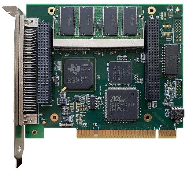
Form Factor Dimensions[attr rowspan=”4″], Desktop PCI (3/4 size): 9″/23cm(L) x 4.9″/12.5cm(W)
PCI-104: 3.55″/9.02cm(L) x 3.775″/9.59cm(W)
3U CompactPCI: 6.3″/16cm(L) x 3.94″/10cm(W)
PMC: 5.86″/14.9cm(L) x 2.9″/7.4cm(W)
Weight, 0.31lbs/140 grams
Supply Voltages, +3.3Vdc @ 1.5A; ±12Vdc supplies passed on to expansion connector and not used by onboard circuitry
Power, 4.5 Watts typical with 128MB SDRAM
Temperature, Commercial grade 0º-85ºC. Consult factory for availability of industrial and military temperature grades
[/table]
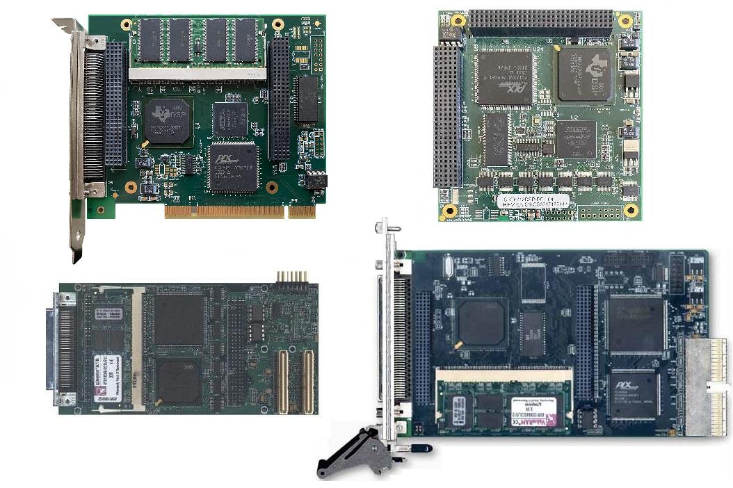 SI-C6713DSP Family
 SI-C6713DSP-PCI
 SI-C6713DSP-PCI104
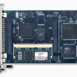 SI-C6713DSP-cPCI
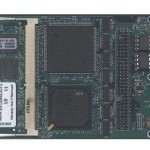 SI-C6713DSP-PMC