SI-MOD32xx
-
 SI-MOD32xx
 -
 SI-MOD32xx
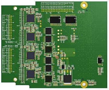
The SI-MOD32xx FMC Expansion I/O Module.
The SI-MOD32xx is a family of high resolution, FMC form factor, high channel count multi function data acquisition and control modules that plug into any SI-DSP or FPGA carrier card.
Analog Inputs
Each card features up to four (4) parallel ADC circuits, each with up to 8SE/4DE analog input channels where the total count may add up to 8SE/4DE, 16SE/8DE or 32SE/16DE. Each ADC circuit is comprised of its own multiplexer, programmable gain instrumentation amplifier and ADC. Up to four (4) distinct channels, one from each circuit, can be simultaneously sampled. Each ADC’s resolution is 16 bits with sampling rates ranging from 0hz to 1Mhz. The maximum high impedance bipolar input voltage level is ±24.576Vp, with seven (7) gain values ranging from 0.16 to 6.4, along with a 482Khz 1-pole lowpass smoothing filter. The ADCs are based on a Successive Approximation architecture, which makes them ideal for control applications. Each input’s termination can be individually programmed for single or differential ended operation, thereby not limiting you to an all-or-nothing configuration.
Analog Outputs
There’s the option of two (2) parallel DAC circuits with eight (8) analog outputs each, where the total count may add up to sixteen (16) channels. The DAC resolution is 16 bits, and can update at rates up to 250khz per channel. The outputs are programmable as either unipolar with ranges of 0V-2.5Vp, 0V-5Vp, or 0V-10Vp, or bipolar with ranges of ±5Vpp or ±10Vpp.
Digitally Controlled Calibration
An on board 32KByte EEPROM contains the offset and gain errors which are loaded into the DSP or FPGA and used to implement real time digital calibration on all analog I/O.
Digital I/O
Thirty two (32) general purpose digital I/O lines may be configured as a pair bidirectional, buffered 16 bit ports. These lines are in addition to any of the digital I/O lines native to the SI-DSP or FPGA carrier card.
FMC Interface
The FMC Low Pin Count (LPC) interface is all that is necessary when only the analog IO circuitry is required. However, the FMC High Pin Count (HPC) interface is necessary if the digital IO circuitry is required. The industry standard FMC interface allows for maximum flexibility for clocking and control, with 2.5V-3.3V LVCMOS signal levels to interface to all ADCs, DACs, and digital IO buffers.

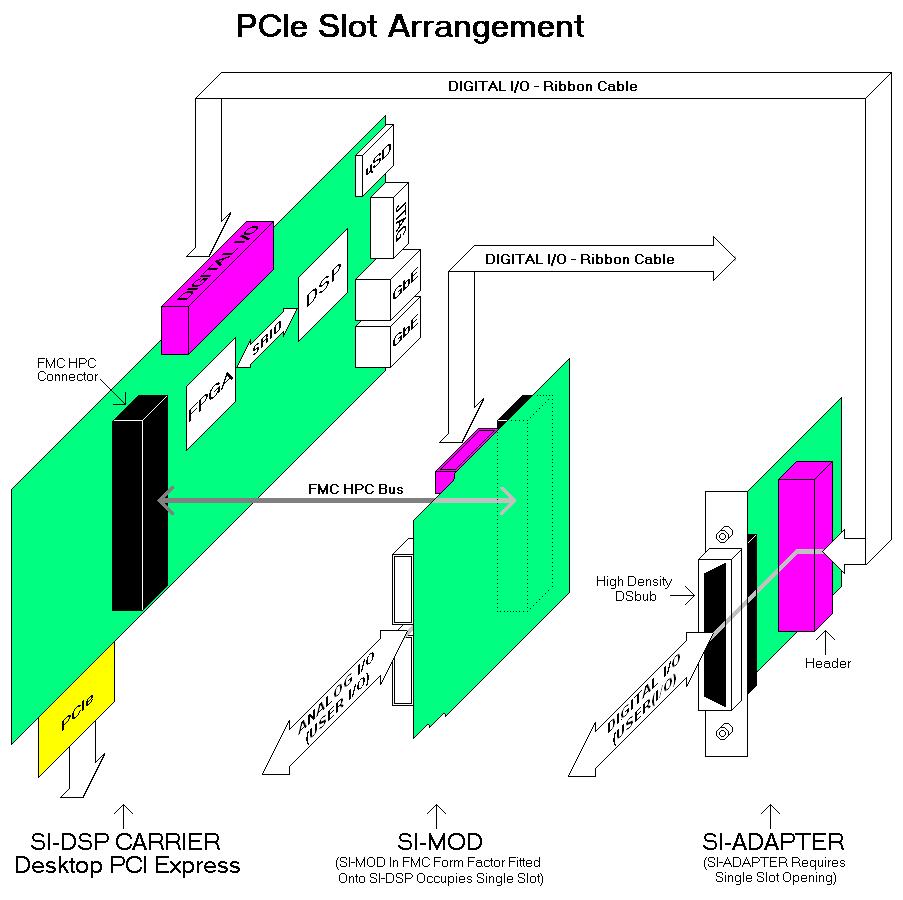
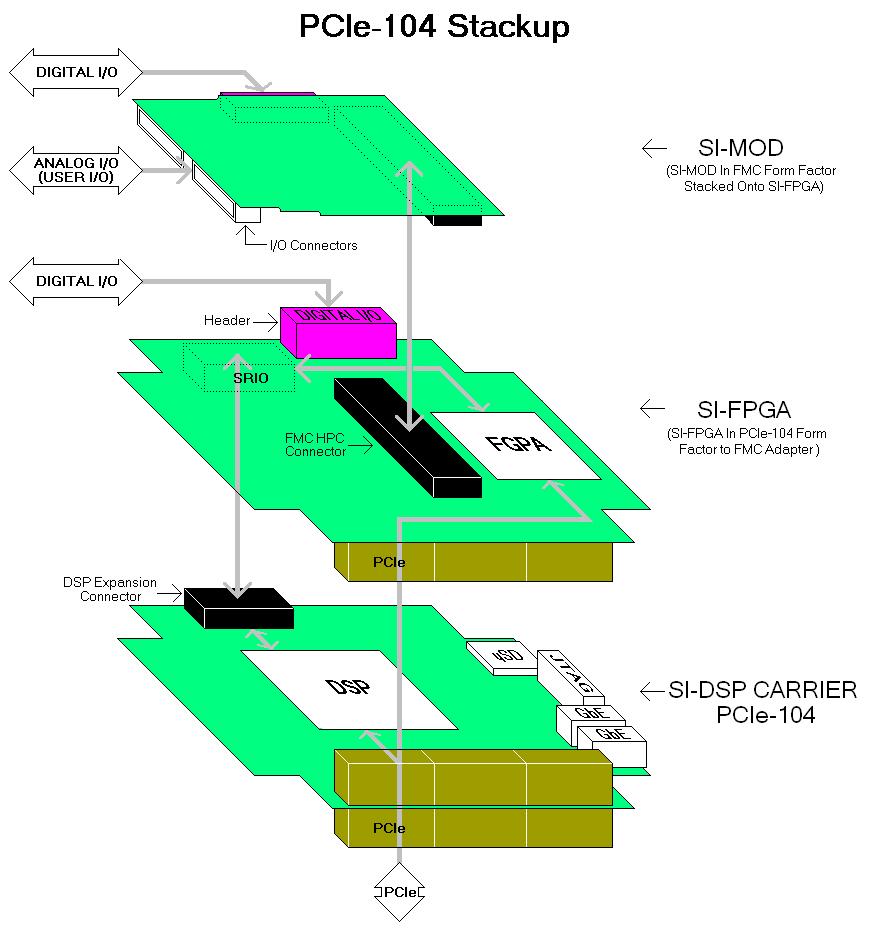
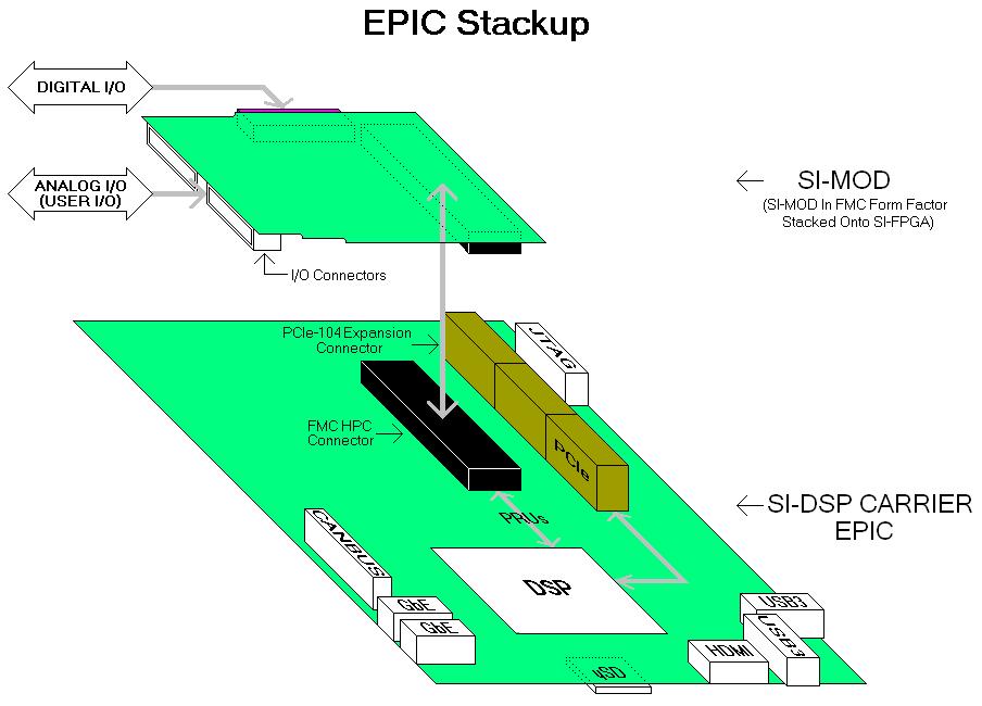
All functions for the SI-MOD32xx are fully programmable via the HPC interface, with support files for Altera or Xilinx FPGAs (Lattice supplied upon request).
For more detailed documentation, check out the SI-MOD32xx Wiki Homepage
Connectivity
[table class=”siTB”]
Expansion Interface[attr colspan=”2″]
FMC [attr rowspan=”3″], LPC for Analog IO Circuitry exclusively; HPC for Analog & Digital IO Circuitry
FMC Vadj Range: 2.5V-3.3V LVCMOS signaling
Clock Speed: up to 50Mhz
30 Pin Headers [attr rowspan=”2″], 1st Header: up to 16 Analog Inputs and 8 Analog Outputs
2nd Header: up to 16 Analog Inputs and 8 Analog Outputs
40 Pin Header, 32 bit digital IO
[/table]
Analog Inputs
[table class=”siTB”]
Analog Input Section[attr colspan=”2″]
Input Termination[attr rowspan=”4″], SI-MOD3208: 8S/4D; 0hz to 1Mhz additive sampling for all channels
SI-MOD3216: 16S/8D; 0hz to 2Mhz additive sampling for all channels
SI-MOD3232: 32S/16D; 0hz to 4Mhz additive sampling for all channels
Flexible Input Termination; each channel individually programmable for differential or single ended operation
Input Characteristics [attr rowspan=”4″], Bipolar (Differential) Input Voltage Level: ±0.64Vp (1.28Vpp) to ±24.576Vp (49.15Vpp) maximum
Impedance: minimum 1Mohm
Coupling: DC
Input Smoothing Filter: Fixed 482Khz 1-pole lowpass smoothing filter.
Fully Integrated MUX-PGA-ADC Circuitry [attr rowspan=”4″], p/n ADAS3022 (Analog Devices)
Mux: 8SE/4DE channels (each ADC)
PGA (±Vin): 0.16 (±24.576Vp); 0.2 (±20.48Vp); 0.4 (±10.24Vp); 0.8 (±5.12Vp); 1.6 (±2.56Vp); 3.2 (±1.28Vp); 6.4 (±0.64Vp)
ADC: Successive Approximation ADC; 1Mhz @ 16 bits
[/table]
Analog Outputs
[table class=”siTB”]
Optional Analog Output Section[attr colspan=”2″]
DAC Count Options [attr rowspan=”2″], -8DAC: 8 Analog Outputs
-16DAC: 16 Analog Outputs
DAC Circuit, p/n LTC2666 (Linear Technology)
Update Rate, 0hz to 250Khz per channel
Programmable Output Voltage Level[attr rowspan=”2″], Bipolar: ±2.5Vp; ±5Vp; ±10Vp
Unipolar: 0V-5V; 0V-10V
[/table]
Digital I/O
[table class=”siTB”]
Optional Digital I/O Section[attr colspan=”2″]
32 General Purpose Discrete I/O[attr rowspan=”2″], 32 line bi-directional port with programmable directional control as two individual 16 bit ports. Nominal +3.3Vdc CMOS/TTL logic levels; directly tied to 74FCT2652 class of bidirectional buffers
[/table]
General Features
[table class=”siTB”]
General Features[attr colspan=”1″]
Industry Standard FMC Interface
On board 32KByte EEPROM contains offset/gain errors; loaded to FPGA for real time digital calibration on all analog I/O
Full suite of development tools from Sheldon Instruments
Windows and Linux 32/64 bit application and driver support
[/table]
Mechanical Properties
[table class=”siTB”]
Physical Dimensions/Electrical Requirements/Temperature[attr colspan=”2″]
Dimensions, single width: 3.3″/8.4cm(L) x 2.7″/6.9cm(W)
Weight, 0.18lbs or 85 grams
Supply Voltages[attr rowspan=”2″], Vadj: +2.5Vdc to +3.3Vdc for FMC interface circuitry
+12Vdc: Used to generate ±15Vdc for analog circuitry; +5Vdc for analog and digital IO buffers.
Power[attr rowspan=”2″], 2 Watts typical with minimum configuration: +15Vdc@0.04A; -15Vdc@0.04A; +5Vdc@0.12A; Vadj@0.033A
7 Watts typical with maximum configuration: +15Vdc@0.17A; -15Vdc@0.17A; +5Vdc@0.12A; Vadj@0.033A
Temperature, Commercial grade 0°-85ºC. Consult factory for availability of industrial and military temperature grades
[/table]
Multifunction I/O Module with 1MHz ADCs
[table class=”siTB”]
Product, Description, Price (US dollars)
SI-MOD3208, 4D/8S analog in – x1 SAR 16 bit ADC @1Mhz – gains 0.16 to 6.4 – 32 digital I/Os, 895
SI-MOD3216, 8D/16S analog in – x2 SAR 16 bit ADC @1Mhz – gains 0.16 to 6.4 – 32 digital I/Os, 995
SI-MOD3232, 16D/32S analog in – x4 SAR 16 bit ADC @1Mhz – gains 0.16 to 6.4 – 32 digital I/Os, 1195
[/table]
DAC Options for SI-MOD32xx
[table class=”siTB”]
Option, Description, Price (US dollars)
-8DAC, Add “-8DAC” to part number. x8 analog outputs, 150
-16DAC, Add “-16DAC” to part number. x16 analog outputs, 300
[/table]