Introduction
Precision Time Protocol (PTP) defined in IEEE 1588 standard is used to synchronize clocks throughout a computer network. Despite a lack of presence, it may prove to be a highly valuable implementation for embedded systems and real time processing applications that include Additive Manufacturing, Image Processing, Test & Measurement, Military & Aerospace to name a few.
Precision Time Protocol daemon (PTPd) is a popular open source program that implements PTP based purely on a software stack under Linux. This article will demonstrate the basic concepts and aspects of migrating PTPd to an SI-C6678 DSP embedded board running a Real Time Operating System (RTOS). For this effort, we should keep two tasks in mind:
- Make minimal code changes and maintain existing API calls, thereby making it easier to migrate future versions of PTPd.
- Add RTOS and hardware features to improve the performance of PTPd.
Description of Hardware, RTOS, and Development Environment
The SI-C6678DSP is a powerful KeyStone I Multicore Digital Signal Processor (DSP) card.
TI-RTOS Kernel (formerly known as SYS/BIOS™).
Code Composer Studio (CCS) is an integrated development environment (IDE) that supports the entire portfolio of TI Microcontrollers and Embedded Processors.
PTPd Files Breakdown
Files under ./src path are core functions for PTPd, and no modifications should be made.
Files under ./src/dep path contain system dependent code, their functions are implemented by calling Linux system routines. Only some files need to replaced under this directory.
./src/dep/net.c
Initializes network connection and opens up sockets for the exchange of PTPd packets.
./src/dep/servo.c
Sets and adjusts the clock used by PTP.
./src/dep/sys.c
Sets and obtains the internal time maintained by PTP.
./src/dep/timer.c
Implements timers used by the PTPd state machine.
PTPd Structure Brief
PTPd implements a state machine handling PTP packets and interacting with remote clocks. After configuration is set, function ‘protocol’ will be called. This function will run in an infinite loop and timers will be used to drive the state machine. When a timer expires certain actions will be taken, like resend PTP packets. PTPd uses the Linux system clock to sync with remote clocks, the Linux socket library to listen and exchange Ethernet PTP packets, and also relies on a software network stack to provide the time stamp for its packets. When we port PTPd to TI RTOS Kernel, we need to replace Linux specific functions with equivalent TI RTOS Kernel modules. We also want to add hardware support to the project. Major modifications will be descried in the following paragraphs.
Timer
PTPd uses timers to resend PTP packets. Timers are initialized by setting up a Linux signal handler, where a global counter resides and is increased every cycle. The state machine will call the ‘timerExpired’ function to check whether timers are expired. The ‘timerExpired’ function explicitly calls the ‘timerUpdate’ function which adds up the global counter value to each timer.
TI RTOS Kernel provides a Timer module. We can easily replace the pseudo timer with the Timer module. When ‘initTimer’ is called, we set up timers and its handler by invoking the Timer module API ‘Timer_create’ call. We can pass the index of the timer to the handler. We will use the same function name ‘catch_alarm’ for our handler so it will be equivalent to void ‘catch_alarm(int index)’. The handler will be called by the system whenever a timer maintained by TI RTOS Kernel expires. The timer is automatically stopped, so all we need to do inside the handler is set up the expired flag based on the index value.
Later on, when ‘timerExpired’ is called, the flag is checked and the corresponding value will be returned. When ‘timerStart’ is called, we simply invoke the Timer module API ‘Timer_start’ call in order to start/re-start timers. Timer module is simple and intuitive, however it brings up a very important aspect of the RTOS: multi-threading.
Multi-Threading
TI RTOS Kernel provides four different levels of threads: Hwi, Swi, Task and Idle.
Hwi has the highest priority, will not be interrupted by other threads but can interrupt other threads. Hwi threads are usually handlers for hardware triggered interrupts such as ‘Timer64’ and ‘Ethernet Switch’ for packet time stamping that we will describe in detail later.
Swi has priority lower than Hwi but higher than Task. Swi threads are usually handlers for software triggered interrupts such as the Timer module mentioned above.
Task and Idle have the lowest priority. They keep be running until Hwi or Swi interrupts them. Task has different levels of priority, while Idle is basically the lowest priority task. We use the Task thread to run the state machine of PTP.
The function ‘setTime’ should be an atomic operation that is used to set the current time maintained by software. In order to do so, we use TI RTOS Kernel ‘GateAll’ module which can protect a critical section being interrupted by other threads. After calling ‘GateAll_enter’, all interrupts are disabled. Therefore, Hwi like interrupts from Timer64 will not work. When we leave the critical section, we call ‘GateAll_leave’ and interrupts are re-enabled.
Clock
We will use hardware Timer64 to simulate the clock for PTP. Timer64 is a hardware module provided by the board, and it should not be confused with the software Timer module.
We will register a ‘Clock_tick’ handler for the Timer64 interrupt. The counter will be increased on every input clock cycle in Timer64. When the counter is equal to the value we set in the Timer Period Registers, the Timer64 module will trigger an interrupt to our software, and our ‘Clock_tick’ handler will catch it. PTP requires 48 bit data to represent internal data, 16 bits for seconds and 32 bits for nanoseconds. We will maintain two global variables for seconds and nanoseconds in our software. Each time the handler is called, we convert and add the period value to our global seconds and nanoseconds variables.
Time Stamping
The Gigabit Ethernet (GbE) Switch subsystem on the board provides a Common Platform Time Sync (CPTS), which has the ability to time stamp incoming and outgoing PTP packets. This will improve the time stamp precision rather than relying on the software network stack to do so. For the KeyStone 1 platform, it can detect PTP packets based on Annex F in the PTP standard.
Since we use Timer64 for our PTP clock, there is a time difference between CPTS and Timer64 when the time stamps are processed by our software, with adjustments thereby requiring further calculations.
We select 1/3 system clock as clock source for the CPTS. Each rising edge will increase the 32 bit counter in the CPTS. The time stamp provided by the CPTS can be converted using the following formula:
\[\begin{aligned}
\ T_{CPTS} = \frac{N_f(0XFFFFFFFF+1)+TimeStampCPTS}{ F_{sys} \frac{1}{3}}\\
\end{aligned} \]
\(T_{CPTS}\) is the time result
\(N_f\) is the number of times the counter has flipped
\(F_{sys}\) is the frequency of the system clock
\(TimeStampCPTS\) is the current time stamp value
The clock source for Timer64 is the system clock, so:
\[\begin{aligned}
\ T_{Timer64} = \frac{TimeStampTimer64}{F_{sys}}\\
\end{aligned} \]
The time difference should be:
\[\begin{aligned}
\ \Delta T = T_{CPTS} – T_{Timer64}\\
\end{aligned} \]
Since the same clock source is used by CPTS and Timer64, the time difference should remain the same during run time.
When there is an offset between our local clock and the remote clock, we add DeltaT to the offset and use the result to adjust the local clock frequency and set the corresponding period value in Timer64.
Network
TI provides a Network Development Kit (NDK) with support for socket operations. It is easier for us to port the Ethernet connection layer.
Notice that not all socket options are supported by TI NDK. For example, we are unable to configure the IP_MULTICAST_LOOP option. Therefore, every time a multicast packet is sent out, we need to explicitly send the packet to the local host to simulate the same behavior.
Work Flow
The run time work flow of the project can be break down as the below chart:
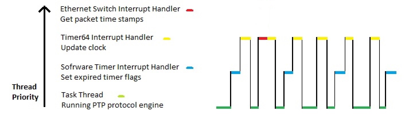
Notice that the scales for each line in the chart are abstract, they do not represent run time percentages for each thread. In reality, interrupt handlers should have less codes and only occupy small time intervals.
Conclusion
As we break down the steps necessary to port PTPd from Linux to an RTOS, it becomes evident the ease with which can port a large operating system program to an embedded system environment. With flexible multi-thread handling and rich hardware peripheral support, the ported program in an embedded system running an RTOS has significantly more capabilities.